Translated: Initialization and GPIO Development
Establishing Connection#
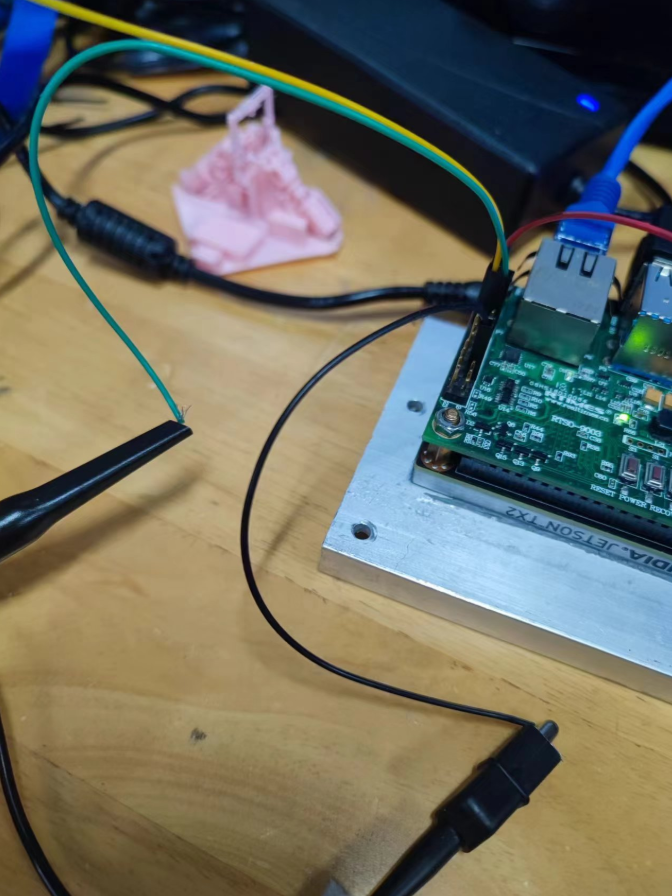
Connect the Jetson to your computer using an Ethernet cable.
In the Network Sharing Center, share your current network connection to the Ethernet interface. If you're unsure which port is being used, power on the Jetson first - the unidentified network that appears will be the Jetson. Upon successful connection, a connected indicator will appear on the Jetson interface.
The installation processes for Anaconda, PyCharm, etc., won't be detailed here. Create a virtual environment and install Jetson.GPIO via PIP.
Environment Configuration#
Import the Anaconda environment in PyCharm. If prompted about missing interpreters, first use the conda env list command in your terminal (regardless of whether the environment is activated) to locate the base environment (typically under username/miniforge3). The conda executable can be found in the bin folder of this directory. Then select "Load Environment."
Testing GPIO Functionality#
During testing, it was discovered that since I'm not using the official carrier board but a third-party one, the Jetson.GPIO library couldn't be utilized. This necessitates alternative approaches. First, consult the carrier board's user manual—for instance, I'm using the RTSO-9003, whose manual is available in the official legacy documentation repository.
My carrier board employs a non-standard 24-pin IO interface, differing from the official 40-pin layout. If your third-party carrier board uses the standard 40-pin interface, I still recommend using the Jetson.GPIO library. Otherwise, you might consider using my open-source XyGPIO library (though it may not be fully completed yet).
Currently, the exposed GPIO pins are 388, 298, 480, and 486. The first two are also available in the official 40-pin configuration but still couldn't load the Jetson GPIO settings. Fortunately, Linux natively supports GPIO through Sysfs (Windows has supported this since version 8 as well, so for Win IoT development boards, you might try the OS-native method first).
Operating Sysfs requires administrator privileges. Launch the terminal and refer to python - How to perform GPIO read/write operations in Linux? - Developer Home - SegmentFault. We first need to use the EXPORT function to make the GPIO accessible at the user level. Note that this operation is temporary and must be repeated after each system reboot.
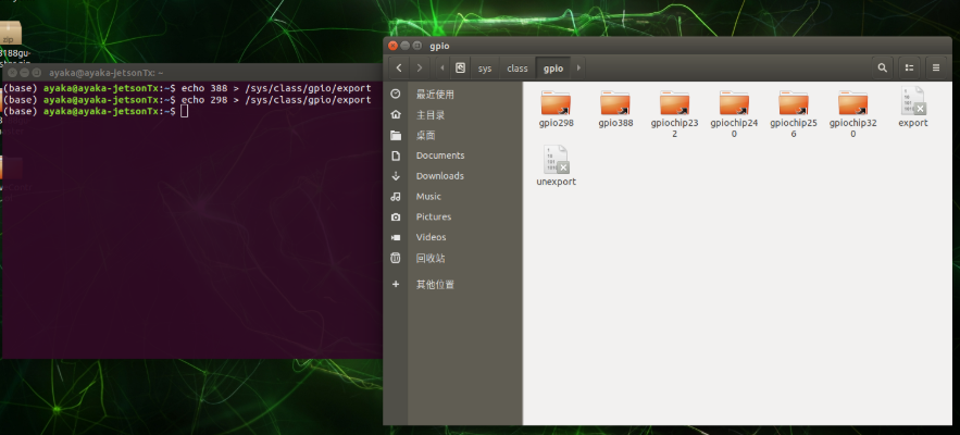
All functional interfaces are located in /sys/class/gpio. The command to expose an interface is echo [pin number] > /sys/class/gpio/export. Open this path in your file manager, and if successful, you should see a folder named GPIO[pin number].
If you opened this folder before configuration, you might not see changes immediately—try reopening it.
Opening the corresponding folder reveals the following contents:
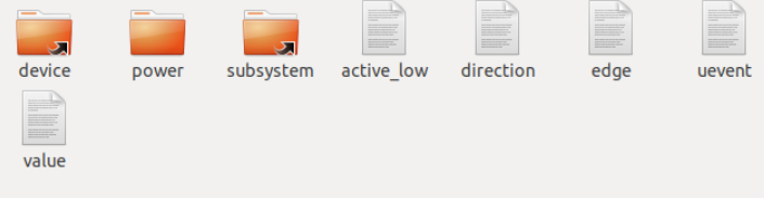
We primarily interact with Direction and Value.
Direction can be set to in or out to configure the pin as input or output. You can modify this file directly using commands like:
echo in/out > /sys/class/gpio/gpio[pin number]/direction
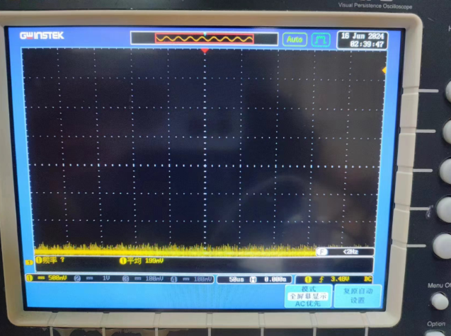
Connecting the target pin to an oscilloscope shows that the pin voltage drops from the default 3.3V to 0V immediately upon configuration.
When making connections, ensure you use Dupont cables plugged into the interface rather than alligator clips. Locate the GND pin during measurement.
Next, test basic GPIO functionality by changing the value content. The command is:
echo 1 > /sys/class/gpio/gpio[pin number]/value
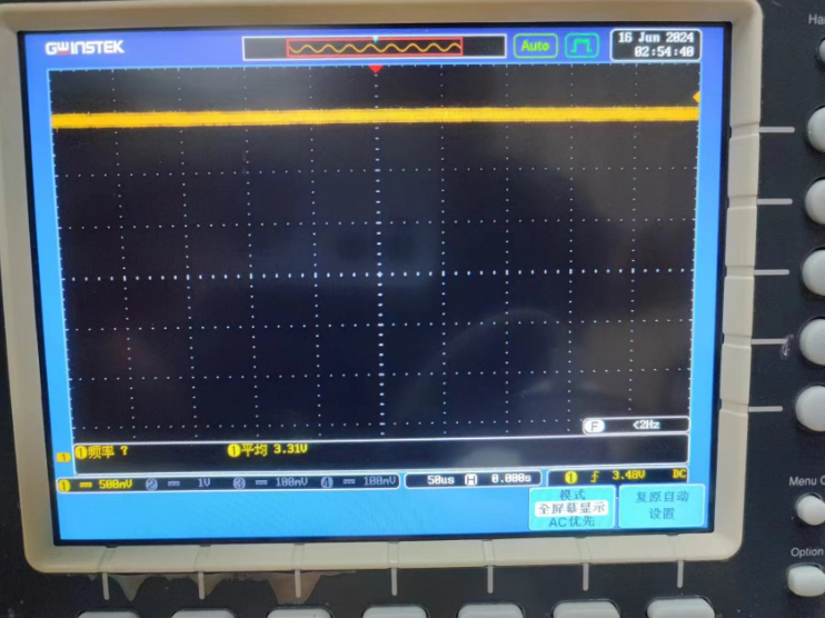
The oscilloscope should now display 3.3V.
Automation#
We can see that GPIO operations essentially involve file operations, which we can replicate in Python.
Note: During testing, ensure the sysfs mapping corresponds to your device's pin configuration.
def writeBit(IOnum, value, DebugFlag = False):
    os.system(f'echo {value} > /sys/class/gpio/gpio{IOnum}/value')
    if DebugFlag:
        print(f"XyGPIO:WriteBit:{value} into {IOnum}")
Calling writeBit(298, 0) shows the oscillometer reading drop to 0. This function will be included in the XyGPIO library.
There's no need to manually switch another pin to input mode via command—we can automate mode setting as well.
def setMode(IOnum, mode, DebugFlag = False):
    os.system(f'echo {mode} > /sys/class/gpio/gpio{IOnum}/direction')
    if DebugFlag:
        print(f'XyGPIO SetIO:{IOnum} as {mode}')
Test with setMode(388, 'in'). The oscilloscope won't show changes, but we can verify the setting with:
cat /sys/class/gpio/gpio388/direction
Successful configuration shows:

Check the current probe value with cat /sys/class/gpio/gpio388/value, which should be 1.
Using the oscilloscope's alligator clip, connect GND to the configured pin and check again—the reading should now be 0.
Next, automate reading:
def readBit(IOnum, DebugFlag = False):
    value = os.popen(f'cat /sys/class/gpio/gpio{IOnum}/value').read()
    value = int(value)
    if DebugFlag:
        print(f"XyGPIO:ReadBit:{value} in {IOnum}")
    return value
Testing with readBit(388, 1) yields terminal output: XyGPIO:ReadBit:0 in 388, matching the command-line result.
Two pins remain unconfigured. Let's automate the EXPORT operation:
def exportIO(IOnum, MessageFlag = True):
    os.system(f'echo {IOnum} > /sys/class/gpio/export')
    if os.path.exists(f'/sys/class/gpio/gpio{IOnum}/value'):
        if MessageFlag:
            print(f"XyGPIO exported at {IOnum}")
    else:
        print("XyGPIO:Failed To Export! Are you sure port exists?")
Test with exportIO(480), and the gpio480 folder should appear. An sh: echo: I/O error indicates the pin was already exported.
Further automation:
def initIO(IOnum, mode):
    exportIO(IOnum, 0)
    setMode(IOnum, mode)
Basic functionality testing is now complete. Note: While there's an unexport operation, avoid using it as it forces a device reset. Instead, write a test program that disconnects the oscilloscope probe, reboots the device, and verifies the full workflow:
if __name__ == "__main__":
initIO(388, 'in')
initIO(298, 'out')
time.sleep(3)
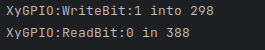
writeBit(298, 1, True)
readBit(388, True)Expected output: